


Following Tutorial is old. Please follow new PPP installer tutorial.
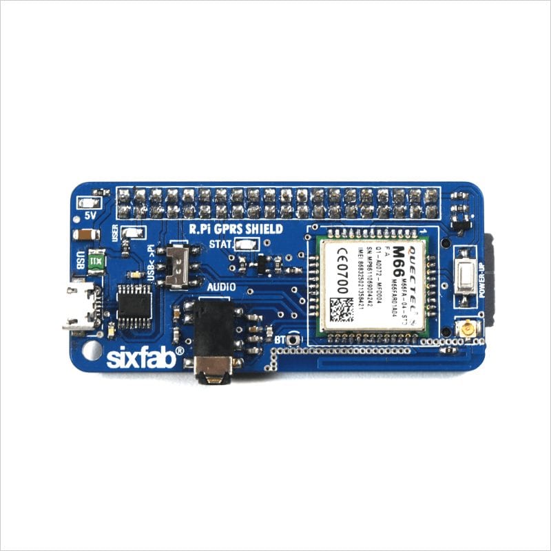
Sixfab GSM/GPRS Shield is using Quectel M66 GSM/GPRS module. It bears the optimal performance in SMS, Data transmission and audio service. Due to the small size(equal to size of raspberry pi zero) it is easily embeddable in any project like video streamer, establishing Internet connection, security systems, tracking system etc.
Features:
• It is a quad-band module(850/ 900/ 1800/ 1900MHz).
• Works on 3.3V ~ 4.6V(which is provided by the Raspberry Pi) No external power supply required.
• Operates at -35°C ~ +80°C.
• Supports Bluetooth BT 3.0 , Voice support
• Controlled via AT commands
• Autobauding 4800bps to 115200bps
• Maximum download speed 85.6kbps
• Uses UART ports or USB port (switchable port)
Now we will use this shield to create PPP (Point to Point Protocol) internet connection. Elaborated steps are stated below.
So the shield comes a 2×20 pin female header.

Sixfab GSM/GPRS shield
1. The header is later soldered with the shield.

Soldered Header
2. Once soldered SIM is inserted.

Inserting SIM
3. Since the shield can be used either with UART or USB. It is needed to be selected with the switch available on the the shield. We select Pi here.

USB<>Pi Switch
4. Now it is connected to Raspberry Pi 3 Model B.

Shield with Raspberry Pi 3 model B
5. Connect Raspberry Pi to internet via WiFi or Ethernet.
Open the terminal(if you are using desktop or laptop you may connect raspberry pi with SSH. Also enable ssh from the Menu > Preferences > Raspberry Pi Configuration as shown in the figure below)

Raspbian interface

Raspberry Pi Configuration
6. Once Raspberry Pi is connected, run following command in order to update Raspberry Pi.
sudo apt-get update

Update command in Terminal
7. Now the getty service needs to be stopped on Raspbian. Getty manages a terminal line and it protects the system from unauthorized access. By default GPIO14 and GPIO15 of Raspberry Pi are active as console. So it need to be disabled as serial console is not being used. Moreover the service of serial console is to be deleted from cmdline.txt. Run the following commands (terminal is connected to /dev/ttyS0 in this case)
sudo systemctl stop serial[email protected] sudo systemctl disable serial[email protected]
As in previous versions Raspberry Pi terminal is connected to /dev/AMA0, following commands should be used instead.
sudo systemctl stop [email protected] sudo systemctl disable serial-[email protected]

Stopping getty
8. Now console has to be removed from the cmdline.txt. This can be done by running following command
sudo nano /boot/cmdline.txt
and removing ”console=serial0, 115200” or ”console=ttyAMA0, 115200” for Raspberry Pi other than version 3. Exit editor saving the changes.

Removing “console = serial0, 115200”
Now Raspberry Pi is rebooted.
9. UART is enabled by adding ”enable_uart=1” at the end of text which is obtained by following command
sudo nano /boot/config.txt

Adding “enable_uart=1”
10. In this step minicom will be installed, which is a serial communication program.
sudo apt-get install minicom
command will install the minicom to the Raspberry Pi.

installing minicom
11. The settings will be configured now by
minicom -s

Opening minicom

minicom settings
12. Serial port setup is selected

Selecting Serial port setup
This brings up following screen

Serial Port setup Screen
13. Following changes are to be made
Serial Device: /dev/ttyS0 and Hardware Flow Control: No

Changing Settings
14. The setup is saved as default

Saving the changes
This will open minicom screen.

minicom screen
15. In order to check either it working or not type ‘AT’ and enter. If it responds with ‘OK’ then its working properly.
For exiting this press CRTL-A Z then follow instructions

minicom screen

minicom screen

minicom screen

Indicating Power Up Button
16. Now before moving to next step POWER UP the shield with the press button available on the shield. Then blue led of State will blink which indicates successfully powered up of the shield.
The shield can also be Powered Up by making GPIO 25 HIGH for 2 seconds and then LOW, as GPIO 25 is connected to POWER KEY of the shield.
Pin assignment of the shield is provided below.

Pin Assignment of shield
17. This step includes the connection tutorial
Here ppp-creator.sh is to be downloaded. Installation is done with following commands:
wget https://raw.githubusercontent.com/sixfab/rpiShields/master/tutorials/tutorial2/ppp-creator.sh chmod +x ./ppp-creator.sh sudo ./ppp-creator.sh HOLOGRAM ttyS0
In the last command HOLOGRAM is the APN of the network operator. ‘ttyAMA0’ will be used instead of tty0 in case of other versions of Raspberry Pi.
18. Now the shield is ready to connect to internet. Disconnect Raspberry Pi from WiFi or Ethernet.
Type
sudo pppd call gprs
or
sudo pppd call gprs&
Here & sign is used to run the command in background.
(Open a browser and check a website)

Connecting to Internet
19. Just to check the status of shield and ip, type
ifconfig ppp0

Checking IP and status